
|
SADCO-Dock
Computer control system of dock operations of floating docks SADCO-Dock  Computer control and monitoring system for dock ballast system (CCS DBS) is intended to control docking operations in manual remote or automatic remote modes. The ballast system is one of the most critical systems on the floating dock. Operation of this system must be finely adjusted with the requirements of the marine industry. AMICO Ltd has multi-discipline competence and broad experience for marine industry applications. AMICO Ltd is a knowledge based company that offers high-tech solution to support safe control and monitoring of the entire dock ballast system. This fully integrated dock ballast system solution provides safe and reliable operations of dock facilities in real life harsh conditions, reduces risks to vessels and generates both operational and financial benefits to customers. The CCS DBS system is specially designed for control of dock ballast operations and of processes of vessels docking. The system can be customized according to the project specific requirements. The System provides:
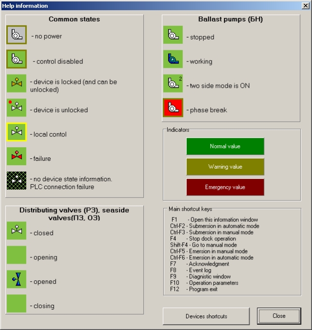
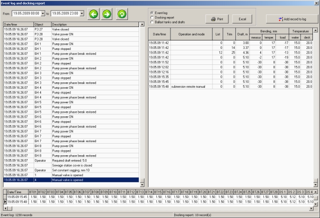
Description of system operation CCS DBS is designed as a hierarchical system with the distributed microprocessor facilities. Control system architecture is two-level: upper and lower control levels. Upper level provides centralized monitoring of docking parameters, and performs remote automatic and remote manual control of dock operations. Two computers (main and standby), two central processor units (CPU) (main and standby) are used as upper level. CPU is a programmable logical controller (PLC) with a built-in Programmable Read Only Memory for operational system and Random Access Memory for application programs. This highly reliable controller is designed for multiple arrangements, extended temperature ranges, immunity to electrical noise, and resistance to vibration and impact. The programmable controller realizes control tasks in real-time mode and follows the algorithm of the docking procedure. Lower level is designated for gaining primary measuring and signaling information and delivery control signal for start-up instrumentation of mechanisms. Also it is designated for delivery measuring and signaling information to upper level. The organization of input/output operations is done by means of input/output (I / O) modules through network interface. I / O modules transform signals of different sensors into format of signals which can be processed by CPU and form output signals for actuating mechanisms. I / O modules are installed in boards of automation. These boards are installed in place of location of control equipment. The control of units and devices of technological equipment is based on “impulse” control principle, i.e. control signals is switched on as an impulse long enough to execute the respective command. Hot standby The Hot standby technology is provided to secure high reliability of CCS DBS. Hot standby technology is based on using second control system, which has configuration identical to the main control system. If a fault is detected, switchover to the standby system is triggered. Synchronization of the standby computer takes place automatically and at high speed. Centralized monitoring is realized from the main computer monitor. At the same time on the standby computer monitor the same information is displayed providing the possibility to get any information and open any windows, but ballast dock system control is disabled. If the main computer is failing, ballast dock control functions are switched to the standby computer. The system reliability is based on using standby controller – second control system. Two control systems which have the same configuration communicate with each other through the special hot standby modules, located on the backplane of the main control system and standby control system, and connected with each other through special fiber optic cable. This communication channel allows standby controller to monitor the current status of the main (primary) controller. If the main controller fails, control system switches to the standby controller automatically. Execution of critical processes in the remote input/output (RIO) network doesn’t disconnect because of malfunction in the hardware of the controller. As a result, higher performance and reduction of downtime is provided. In the beginning of each scan of the main controller RAM and input/output states are transferred to the standby controller through a reliable and high speed fiber optic communication line. Upon switching to standby, the standby controller takes over control with the updated input/output state and memory, providing a smooth transition with the minimal impact on the technological process. After switching the standby controller becomes the main one, and when the switched off controller returns to ready state it becomes the standby one. Standby is also provided in the RIO network, designed to supply the communication between input/output nodes and central processor unit by using double cable, which protects the system from the damage of one of the cables or connection devices. Such flexibility provides coordinated and predictable system behavior, considerably increases the system reliability and capability in real operating conditions. Operator interface Centralized monitoring and control of all dock operations is performed via operator interface from the main system computer located in the Central Operation Station of the dock. Advanced operator interface is playing now an increasingly important role in dock monitoring control system. The operator interface provides all of the traditional human-machine interface functionality. The operator interface is clearly structured, powerful, ergonomic and easy to understand. It ensures all control processes requirements and consolidates control functions for greater efficiency. The operator interface also ensures system security by personal user accounts with password profiles and system interlock functions to prevent incorrect usage of equipment and avoid unsafe conditions. The user interface enables the operator to efficiently supervise and control every detail of the technological process. All information belonging to the monitoring and control, event and alarm management, archived data, messages is structured in functional windows. The main window (Figure 1) contains the technological equipment layout and displays water level in ballast tanks, status of distributing valves, pumps and also visualizes the movement of ballast through pipelines when a certain valve is opened or closed. The main window consists of main menu, toolbar, information panel and technological layout. The technological layout contains control elements. It is possible to perform technological operation by clicking the mouse button on the particular control element.  Figure 1. Main window Possible dock operations, states of devices, symbols of devices, key combinations for operations are listed in the information window (Figure 2).  Figure 2. Information window The event log contains records about device status changes, dock operation and mode changes, actions of operators, monitored parameters reaching warning and alarm limits. The event log is shown on Figure 3.  Figure 3. Event log The failures of devices, computers and controllers with appropriate descriptions are listed in the diagnostics window (Figure 4).  Figure 4. Diagnostics window |
Authorization Spasska 1, 54030 Nikolaev, Ukraine. Tel. +38(0512) 37-78-39, Fax +38(0512) 37-78-11.